
Navigating the HVAC Refrigerant Transition and the Promise of Hydronic Systems for Future-Ready Architecture
The global heating, ventilation, and air conditioning (HVAC) industry is undergoing a significant transformation driven by the phasedown of high-Global Warming Potential (GWP) refrigerants, primarily Hydrofluorocarbons (HFCs). This shift, mandated by international agreements like the Kigali Amendment and domestic legislation such as the U.S. American Innovation and Manufacturing (AIM) Act, presents both substantial challenges and unique opportunities for the Architecture, Engineering, and Construction (AEC) industry.
By Positive Energy staff
The global heating, ventilation, and air conditioning (HVAC) industry is undergoing a significant transformation driven by the phasedown of high-Global Warming Potential (GWP) refrigerants, primarily Hydrofluorocarbons (HFCs). This shift, mandated by international agreements like the Kigali Amendment and domestic legislation such as the U.S. American Innovation and Manufacturing (AIM) Act, presents both substantial challenges and unique opportunities for the Architecture, Engineering, and Construction (AEC) industry.
Challenges include navigating supply chain disruptions, rising costs, and the critical need for comprehensive technical training for new, mildly flammable refrigerants. However, this transition also creates a compelling opportunity to rethink traditional HVAC approaches. Hydronic systems, particularly those powered by air-to-water or ground source heat pumps, offer a robust, energy-efficient, and "technology-neutral" alternative. By leveraging water as the primary heat transfer medium, these systems can bypass the direct impact of future refrigerant changes, offering long-term resilience and enhanced building performance when integrated with a high-performance building envelope. This report explores these dynamics, providing architects with the insights needed to design truly future-ready buildings.
Understanding the Global HVAC Refrigerant Landscape
The HVAC industry is in the midst of a profound transformation, moving away from refrigerants that contribute significantly to global warming. This shift is not merely a technical upgrade but a regulatory imperative with far-reaching implications for building design and construction.
The Kigali Amendment and International Commitments
The Montreal Protocol, an international treaty established in 1987 to protect the stratospheric ozone layer by phasing out ozone-depleting substances (ODS) like chlorofluorocarbons (CFCs) and hydrochlorofluorocarbons (HCFCs), has evolved to address broader climate concerns.1 In a pivotal development, 197 countries adopted the Kigali Amendment in Rwanda on October 15, 2016, expanding the Protocol's scope to include a global phasedown of HFCs.1
The United States formally ratified the Kigali Amendment on October 31, 2022, signaling its commitment to these global environmental objectives.3 Under this amendment, developed nations initiated reductions in HFC consumption beginning in 2019. Most developing countries are slated to freeze their consumption by 2024, with a select few with unique circumstances following by 2028. The overarching goal is to achieve an 80% reduction in HFC consumption over the next 30 years, specifically by 2047.1 This ambitious phasedown schedule is projected to avoid up to 0.5°C of global warming by the end of the century, preventing over 80 billion metric tons of carbon dioxide equivalent emissions by 2050.2 The international consensus and broad participation underscore a collective commitment to mitigating climate change.
The global alignment on HFC reduction, as seen through the Kigali Amendment and its ratification by the U.S., creates a stable and predictable market for low-GWP technologies.1
This global framework provides a clear signal to manufacturers, incentivizing significant investment in research, development, and production of environmentally friendly alternatives for a worldwide market, rather than fragmented national ones. For architects and developers, this predictability reduces the inherent risk of designing and implementing HVAC systems that might quickly become obsolete due to unpredictable shifts in local regulations. The bipartisan support for the AIM Act in the U.S. further reinforces the stability of this regulatory direction, suggesting that a dramatic reversal of the phasedown is highly improbable.7 This consistent global and national policy environment encourages the adoption of advanced, sustainable HVAC solutions.
The U.S. American Innovation and Manufacturing (AIM) Act and EPA Regulations
In the United States, the American Innovation and Manufacturing (AIM) Act, enacted on December 27, 2020, as part of the Consolidated Appropriations Act, 2021, empowers the U.S. Environmental Protection Agency (EPA) to manage the HFC phasedown domestically.1 The AIM Act mandates an 85% reduction in HFC production and consumption from historic baseline levels by 2036.3
The EPA implements this mandate through an allowance allocation and trading program, established by the HFC Allocation Program in the Allocation Framework Rule.3 This program outlines a stepwise reduction schedule: an initial 10% reduction from 2020-2023 baseline levels, a further decrease to 60% of baseline levels for 2024-2028, 30% for 2029-2033, and a final reduction to 15% by 2036 and beyond.3 Restrictions on the use of higher-GWP HFCs in new refrigeration, air conditioning, and heat pump equipment began as early as January 1, 2025.3 The EPA's final rule, issued in October 2023, specifically sets a GWP limit of 700 for most new comfort cooling equipment, including chillers, effective January 1, 2025, effectively ending the production of most R-410A systems.8
Beyond production and consumption limits, the EPA's regulations under the AIM Act impose stringent requirements on existing HFC refrigerants to minimize leaks and maximize reuse.7 These include mandates for leak detection and repair, the use of reclaimed and recycled HFCs, and proper recovery of HFCs from disposable containers, along with meticulous recordkeeping, reporting, and labeling.7 For example, comfort cooling appliances containing more than 50 pounds of HFC refrigerant must be repaired within 30 days if their leak rate exceeds 10%.10 Furthermore, automatic leak detection (ALD) systems are required for large industrial process refrigeration and commercial refrigeration appliances (with a full charge at or above 1,500 pounds) installed on or after January 1, 2026, and by January 1, 2027, for existing systems installed between 2017 and 2026.10 The obligation to use reclaimed HFCs for servicing certain existing HVAC equipment begins January 1, 2029.10
These regulations, while crucial for environmental protection, introduce an "invisible" cost of compliance and an operational burden for building owners and managers. The requirements for leak detection, repair within strict timelines, and the eventual mandatory use of reclaimed refrigerants translate directly into increased operational complexity, labor costs, and potential fines for non-compliance.7 This means that even systems installed before the phase-out dates will incur higher total costs of ownership due to ongoing compliance efforts. Architects should proactively communicate these long-term operational implications to clients, advocating for HVAC system choices that minimize these burdens and offer greater long-term resilience. The emphasis on refrigerant reclamation also indicates that while older equipment can be serviced, the supply chain for servicing will shift, potentially affecting refrigerant availability and pricing.11

Table 1: Key HFC Phasedown Schedule and GWP Limits
The Transition to Low-GWP Refrigerants (A2L Class: R-454B, R-32)
The HVAC industry is rapidly transitioning from R-410A, which has been the industry standard for decades with a GWP of approximately 2,088, to next-generation refrigerants.8 The primary replacements are A2L-class refrigerants such as R-454B, with a GWP of 466, and R-32, with a GWP of 675.8 These new refrigerants offer significantly lower global warming potential, aligning with environmental goals.8
As of January 1, 2025, new air conditioning systems and heat pumps must be designed to use these A2L-class coolants, marking the cessation of R-410A system production.14 While existing R-410A systems can still be serviced, the supply of R-410A refrigerant is expected to become scarce, leading to increased prices for maintenance and repairs on older units.14
A critical difference with A2L refrigerants, unlike their non-flammable predecessors, is their mild flammability.8 This characteristic necessitates updated safety protocols for handling, installation, and servicing.14 This shift from non-flammable R-410A to mildly flammable A2L refrigerants represents a fundamental change in safety requirements for HVAC technicians.8 While "mildly flammable" might appear to be a minor distinction, it mandates entirely new training, specialized tools, and revised safety procedures.14 This is not merely an adjustment in GWP values; it requires a re-evaluation of established industry practices.
This alteration in refrigerant properties introduces a significant risk if not properly addressed through rigorous training and adherence to new standards. Architects specifying A2L systems must recognize that installation and maintenance demand specialized, certified professionals.17 This directly impacts labor availability, project timelines, and potentially liability. It underscores the critical need for robust training programs, such as the ACCA A2L training, which is developed based on ASHRAE Standards 15 (2019), 34 (2019), and UL Safety Standards 60335-2-40 (2019).19 Without adequate preparation, this could become a significant bottleneck in the industry as equipment rollout accelerates.

Table 2: Comparison of Common Refrigerant Types (GWP, Flammability)
Challenges and Disruptions for the Architecture, Engineering, and Construction (AEC) Industry
The refrigerant transition is not a distant concern but an immediate reality impacting every facet of the AEC industry. Architects must be prepared to address these disruptions in their projects, as they influence design decisions, project timelines, and overall costs.
Supply Chain Constraints and Rising Costs
The phasedown of HFC production, particularly the significant cuts in R-410A availability, has already exerted substantial upward pressure on costs for both servicing existing AC systems and installing new ones.15 As of 2024, R-410A production has been cut by 40%, directly contributing to these price increases.15 The ban on R-410A in new equipment, effective January 1, 2025, is anticipated to further tighten supply and drive up prices for any remaining stock, making it a less viable option for new installations or even major repairs on older units.14
The transition to new low-GWP refrigerants like R-454B and R-32, while environmentally beneficial, has not been without its challenges. There are already reports of severe shortages, particularly for R-454B, exacerbated by limited availability of refrigerant cylinders and a surge in demand as manufacturers convert their product lines.17 This has led to contractors experiencing delays of up to 10 weeks to receive orders, directly impacting project timelines, forcing rescheduling of jobs, and even causing companies to turn away new work.23 Such delays and material scarcity inevitably lead to increased project costs, as labor stands idle or expedited shipping becomes necessary. The requirement for reclaimed refrigerants to service existing systems by January 1, 2029 10, while promoting sustainability, could also lead to higher costs for these reclaimed products compared to virgin HFCs, further impacting the long-term operational expenses of buildings.7
Technical and Safety Training Requirements for New Refrigerants
The introduction of A2L refrigerants, which are mildly flammable, represents a significant shift in safety protocols compared to the non-flammable R-410A.8 This necessitates extensive and specialized training for HVAC technicians. Technicians can no longer apply the same handling and installation practices used for R-410A; they require a thorough understanding of proper handling, enhanced leak detection methods, adequate ventilation procedures, and safe evacuation techniques for A2L refrigerants.14
Industry organizations such as ACCA (Air Conditioning Contractors of America) and ASHRAE (American Society of Heating, Refrigerating and Air-Conditioning Engineers) have developed specific A2L safety training programs based on established standards like ASHRAE Standards 15 (2019), 34 (2019), and UL Safety Standards 60335-2-40 (2019).19 These courses cover critical topics such as refrigerant properties, system replacement considerations, refrigerant charge calculation, piping requirements, and charging/recovery procedures.19 The need for certified professionals to handle these new refrigerants means that a shortage of trained labor could impede the adoption and proper maintenance of compliant HVAC systems.17 This training requirement impacts the AEC industry by increasing labor costs, potentially extending project durations due to specialized labor availability, and demanding a higher level of oversight to ensure safety and compliance during installation and ongoing maintenance.
Regulatory Compliance and Enforcement
The EPA is tasked with implementing and enforcing the AIM Act, establishing regulations, and allocating allowances for HFC production and consumption to ensure compliance with the phasedown schedule.5 Failing to comply with these regulations can result in significant penalties and fines, directly impacting a company's ability to operate.7 The EPA has a robust compliance and enforcement system to prevent illegal activity and ensure adherence to the AIM Act's obligations.3
Beyond federal mandates, several U.S. states, including California, Washington, Vermont, and New York, have implemented or are in the process of implementing their own regulations to phase down higher-GWP HFCs.1 These state-level policies can be more stringent than federal requirements and can significantly impact HVACR equipment decisions and supply chains within those jurisdictions.12 For instance, New York's Part 494 regulation includes future prohibitions on HFCs in new HVACR equipment that will differ from EPA's Technology Transitions rule between 2027 and 2034, with new supermarket refrigeration systems requiring refrigerants with GWP less than 10 by January 2034.13 This patchwork of regulations adds complexity for HVACR industry stakeholders, requiring careful navigation to ensure compliance across different project locations.13 Architects and engineers must stay abreast of both federal and relevant state-specific regulations to ensure their designs meet all legal requirements and avoid costly non-compliance issues.
Equipment Availability and Compatibility
The rapid shift mandated by the 2025 deadline, which bans R-410A in new equipment, has compelled HVAC manufacturers to redesign and optimize their product lines for low-GWP refrigerants like R-454B and R-32.8 While major manufacturers like Carrier, Lennox, Johnson Controls, Trane, Mitsubishi Electric, Daikin, and Midea have introduced new compliant systems, the transition has not been entirely smooth.17
The industry has faced equipment shortages, with some manufacturers converting their lines to new refrigerants at different paces.24 This inconsistency can lead to challenges in sourcing specific units, particularly during peak cooling seasons.17 For example, while some manufacturers have adopted R-454B, others like Daikin and Goodman have focused on R-32, leading to regional variations in availability and potential supply chain bottlenecks.23 The need for A2L-compatible tools and equipment, including specialized refrigerant recovery machines, also presents an additional hurdle for contractors.14 Architects must recognize that equipment availability is a dynamic issue, requiring early engagement with manufacturers and suppliers to confirm the refrigerant type and ensure timely procurement for projects.17 This also means that existing R-410A units cannot simply be retrofitted with new A2L refrigerants due to fundamental differences in system design and component compatibility.8

Table 3: Key Challenges and Impacts for the AEC Industry
Hydronic Systems as a Future-Proof Solution
Amidst the challenges of refrigerant transition, a significant opportunity arises for the AEC industry to embrace hydronic systems. These systems offer a robust, energy-efficient, and inherently "technology-neutral" approach to heating and cooling, providing a pathway to long-term resilience and sustainability.
Water as the Heat Transfer Medium
Hydronic systems utilize water (or a water-glycol mixture) as the primary medium for transferring thermal energy throughout a building.25 Unlike traditional direct expansion (DX) systems that rely on refrigerants circulating directly to terminal units, hydronic systems separate the refrigerant cycle (contained within a heat pump or chiller) from the building's internal heat distribution network.25 This fundamental difference offers a distinct advantage: water is significantly more effective for energy storage and delivery than air, approximately 3500 times more so.29
The versatility of modern hydronics technology is unmatched by other heating or cooling methods.27 These systems can be tailored to provide precise climate control, including space heating, domestic hot water, and even specialized applications like snow melting or pool heating, often from a single heat source.25 By circulating heated or chilled water through pipes embedded in floors, walls, or ceilings (radiant systems), or through coils in air handlers or fan coil units, hydronic systems provide even and efficient heat distribution with minimal heat loss.25 This approach also minimizes air temperature stratification and reduces the rate of outside air infiltration or inside air exfiltration, leading to lower heat loss compared to forced-air systems.27 Furthermore, hydronic systems typically require significantly less electrical energy to move heat compared to forced-air systems.27

Table 4: Common Hydronic System Types and Their Applications
Air-to-Water Heat Pumps: Principles and Benefits
Air-to-water heat pumps (AWHPs) are a type of air-source heat pump that extracts heat from the outdoor air and transfers it to water, which is then circulated through a hydronic distribution system for space heating, cooling, or domestic hot water.28 The system typically consists of an outdoor unit and an indoor unit, which can be installed at significant distances from each other.28
AWHPs operate on the principle of a refrigeration cycle, moving heat from a cooler outdoor environment to a warmer indoor space during heating, and reversing the process for cooling.28 Even in cold air, heat energy is present, which the heat pump extracts and transfers indoors.28 The heated water (up to 130°F or ~55°C) can be used for underfloor heating, radiators, or direct hot water supply.28
AWHPs are gaining prominence in the U.S. for new residential construction due to their high efficiency, fully contained and factory-charged outdoor refrigeration systems, and their hydronic delivery capabilities, which facilitate zoning and integration with thermal energy storage.36 While installation costs for AWHPs can be higher than air-to-air systems due to the need for a water distribution system, their potential for long-term energy savings, especially when providing both heating and hot water, can offset this initial investment.35 Studies indicate that AWHPs can achieve significant energy savings compared to traditional heating systems, with some models offering high SEER2 ratings (up to 24).17 Their performance is particularly strong in moderate climates, though advancements are enabling operation in colder temperatures.18
Ground Source Heat Pumps: Principles and Advantages
Ground source heat pumps (GSHPs), also known as geothermal heat pumps, leverage the stable temperature of the earth as a heat source in winter and a heat sink in summer.28 This inherent stability of ground temperature, unlike fluctuating air temperatures, makes GSHPs exceptionally energy-efficient and environmentally sustainable.37
GSHP systems typically involve a ground loop—a network of pipes buried in the earth—through which water or a water-glycol solution circulates, absorbing or rejecting heat.28 This heat is then transferred to or from the building's hydronic distribution system via the heat pump unit.28 GSHPs can provide space heating, space cooling, and dedicated or simultaneous water heating.38 Modern GSHP designs often incorporate variable-speed compressors, blowers, and pumps, utilizing high-efficiency brushless permanent-magnet (BPM) motors to maximize performance and control flexibility.38
The key design considerations for GSHP systems involve a comprehensive understanding of the site's geological and hydrogeological conditions, as these factors critically impact system feasibility and efficiency.39 The design process must integrate lessons learned from past installations and leverage new ASHRAE and industry research to optimize system cost and performance.39 This includes careful equipment selection, proper piping design, and optimized installation practices.39
GSHPs offer substantial energy savings, often reducing heating and cooling energy costs by 50-70% compared to conventional HVAC systems.40 While the upfront cost of GSHP systems, including drilling and piping, is typically higher than traditional systems, significant financial incentives, such as the Investment Tax Credit (ITC) under the Inflation Reduction Act (IRA), can offset these costs, potentially making them less expensive than conventional HVAC systems in many cases.40 The long lifespan of ground loops (50 years or more) and the heat pump equipment (25 years or more) significantly contribute to lower lifecycle costs and reduced maintenance compared to conventional systems.41 This long-term cost-effectiveness and reduced environmental impact make GSHPs a compelling choice for sustainable building design.37
Hydronic Systems for "Technology Neutral" Homes
The concept of "technology neutral" homes, particularly in the context of HVAC, refers to building designs that are resilient to future technological shifts and regulatory changes. Hydronic systems inherently embody this principle, offering a robust solution that minimizes reliance on specific refrigerant types and their associated regulatory burdens.
Water, as a heat transfer medium, is stable and forgiving, making hydronic systems less susceptible to the direct impacts of refrigerant phasedowns.44 While heat pumps (air-to-water or ground source) still utilize refrigerants in their sealed circuits, the vast majority of the building's thermal distribution network relies on water, effectively isolating the building's interior climate control from the evolving refrigerant landscape.25 This means that as refrigerant regulations continue to evolve, the core hydronic infrastructure of a building remains viable, requiring only potential upgrades to the heat pump unit itself, rather than a complete overhaul of the distribution system.41
This inherent flexibility allows for easy upgrades as new technologies emerge, extending the lifecycle and usefulness of the HVAC system.41 For instance, a hydronic system initially paired with a gas boiler could be directly swapped with a water-sourced heat pump system, transitioning to an all-electric comfort system without the need for costly retrofitting of the distribution network.41 This adaptability makes hydronic systems a smart approach to future-proofing HVAC system designs for decarbonization and achieving net-zero emissions goals.41
Furthermore, hydronic systems, particularly radiant heating and cooling, contribute to technology neutrality by promoting superior indoor comfort and air quality without relying on high-velocity air distribution.27 They provide even warmth with no drafts or hot spots and minimize the circulation of dust and allergens, leading to cleaner indoor air.31 This focus on fundamental comfort and health, decoupled from specific refrigerant chemistries, ensures that the building's core environmental performance remains high regardless of future HVAC innovations.
Integrating Hydronic Systems with High-Performance Building Envelopes
The effectiveness of any HVAC system, particularly advanced hydronic solutions, is profoundly influenced by the performance of the building envelope. For architects, understanding this critical interplay is paramount to designing truly efficient, comfortable, and durable structures.
The Critical Interplay: Building Envelope and HVAC System Sizing
The building envelope—comprising the roof, walls, windows, and foundation—serves as the primary interface between the conditioned interior and the external environment.47 Its design directly dictates the heating and cooling loads a building experiences. A high-performance, integrated, and efficient building envelope, featuring optimized thermal insulation and high-performance glazing, can significantly reduce these loads.47 This reduction in thermal demand, in turn, allows for the specification of smaller, less costly, and more efficient HVAC systems.47
Conversely, an underperforming envelope with inadequate insulation or excessive air leakage will lead to higher heating and cooling demands, necessitating larger, more expensive, and less efficient HVAC equipment.48 This oversizing not only increases initial capital costs but also leads to less efficient operation, as HVAC systems are typically sized for peak conditions that occur only a small percentage of the time.48 Therefore, energy-efficient, climate-responsive construction requires a holistic, "whole building design" perspective that integrates architectural and engineering concerns from the earliest design stages.48 Commissioning the building envelope is crucial to identify and rectify issues like air infiltration, leakage, moisture diffusion, and rainwater entry, all of which negatively impact energy performance and indoor environmental quality.47
Optimizing Thermal Performance: Insulation and Airtightness
Achieving optimal thermal performance in conjunction with hydronic systems relies heavily on a well-insulated and airtight building envelope. Passive building principles, such as those advocated by Phius (Passive House Institute US), emphasize continuous insulation throughout the entire envelope without thermal bridging, and an extremely airtight building envelope to prevent outside air infiltration and loss of conditioned air.34
Super-insulation, combined with extreme airtightness, dramatically reduces temperature variation across building surfaces, which is critical for preventing condensation and mold issues.45 For example, Phius certification guidelines specify minimum sheathing-to-cavity R-value ratios for walls and outer air-impermeable insulation values for roofs, which increase in colder climates to maintain desirable interior surface temperatures and prevent interstitial moisture accumulation.49 An airtight envelope also prevents uncontrolled leakage, which cuts heat loss/gain and improves humidity control.49
With a highly insulated and airtight envelope, the building's heating and cooling loads are significantly minimized, allowing for a "minimal space conditioning system".45 This is where hydronic systems, with their ability to deliver heat and cooling precisely and efficiently, become ideal. For instance, hydronic radiant systems embedded in walls or floors can actively regulate heat exchange between interior and exterior environments, dynamically adapting to outdoor weather conditions.51 The integration of such active building envelope technologies with hydronic layers can significantly reduce building energy use while improving indoor thermal comfort.51 The inherent efficiency of hydronic systems is maximized when the building's thermal loads are already minimized by a superior envelope, creating a synergistic effect that drives down energy consumption.
Managing Moisture and Preventing Condensation in Radiant Systems
While hydronic radiant heating and cooling systems offer superior comfort and efficiency, their application, particularly for cooling, requires careful consideration of moisture management to prevent condensation on cold surfaces.30 Radiant cooling systems remove sensible heat primarily through radiation, meaning they cool objects and people directly rather than the air.30 This allows for comfortable indoor conditions at warmer air temperatures than traditional air-based cooling systems, potentially leading to energy savings.30 However, the latent loads (humidity) from occupants, infiltration, and processes must be managed by an independent system.30
The critical challenge for radiant cooling is to ensure that the temperature of the cooled surfaces (e.g., floors, walls, ceilings) remains above the dew point temperature of the room air to avoid condensation.30 Standards often suggest limiting indoor relative humidity to 60% or 70% to mitigate this risk.30 For example, for an indoor temperature of 75°F (23°C) and 50% relative humidity, the indoor air dew point is approximately 55.13°F (12.85°C).52 To prevent condensation, the radiant surface temperature must be maintained at least 5.4°F (3°C) above this dew point, typically around 69-70°F (20.55-21.11°C).52
Effective moisture control strategies, as outlined by Building Science Corporation and Phius, are essential. These include controlling moisture entry into the building envelope, managing moisture accumulation within assemblies, and facilitating moisture removal.53 For buildings with radiant cooling, this often means:
Airtight Construction and Pressurization: An extremely airtight building envelope is crucial to prevent hot, humid exterior air from infiltrating and contacting cold interior surfaces.49 Maintaining a slight positive air pressure within the conditioned space (e.g., 2 to 3 Pa) can further prevent moisture transport from the exterior into the building construction.53
Dedicated Dehumidification: Because radiant systems primarily handle sensible loads, a separate, dedicated outdoor air system (DOAS) or dehumidification system is necessary to manage latent loads and maintain indoor humidity levels below the condensation threshold.30 Phius guidelines, for instance, recommend ventilation systems capable of at least 0.3 air changes per hour (ACH) to bring in fresh air, which may then need to be dehumidified.55 Integrating a cooling coil from the radiant system into the dehumidifier's supply stream can pre-cool the dehumidified air, improving efficiency.55
Smart Controls: Advanced control systems are vital for monitoring both surface temperatures and indoor dew point temperatures. These controls can automatically adjust the chilled water supply temperature to maintain a safety margin (e.g., 5°F or 2.78°C) above the ambient air dew point, preventing condensation while maximizing cooling output.52
Material Selection: For radiant floor cooling, materials with low thermal resistance, such as bare concrete, are ideal to maximize cooling energy output.52 The R-value of flooring directly impacts the required chilled water temperature; higher thermal resistance necessitates colder water to achieve the same cooling flow.52
Architects must work collaboratively with mechanical engineers to design a building envelope that minimizes sensible cooling demand (e.g., 6-10 Btu/hr/ft²) and ensures that interior surfaces remain above the dew point.52 Overlooking moisture control requirements, particularly in humid climates, can lead to significant problems like mold growth and degraded building performance.50
Design Considerations for Architects: Walls, Floors, and Ceilings
The integration of hydronic systems, especially radiant elements, fundamentally alters architectural design considerations for walls, floors, and ceilings. These surfaces become active components of the HVAC system, influencing thermal comfort, energy performance, and even acoustic properties.
Walls: Hydronic piping can be embedded within wall assemblies to create radiant heating and cooling surfaces.25 This requires careful coordination with structural elements and finishes. Climate-adaptive opaque building envelopes with embedded hydronic layers are being developed to dynamically regulate heat exchange.51 Architects need to consider the thermal properties of wall materials, ensuring they are compatible with radiant heat transfer and do not impede the system's efficiency. The airtightness and insulation of walls are critical to minimize heat loss/gain and prevent condensation on the interior surface of the radiant wall.45
Floors: Radiant floor heating is a well-established application, where heated water circulates through tubing laid under the floor.26 For radiant cooling, the floor surface temperature must be carefully controlled to remain above the dew point.30 This implies careful consideration of flooring materials; bare concrete or materials with low thermal resistance are preferred for maximizing cooling output, as they allow for more effective heat transfer.52 The thermal mass of the floor system can also be leveraged for energy storage, especially with electric radiant systems.31 Architects must coordinate slab design, pipe spacing (e.g., minimum 6 inches center-to-center for infloor pipes), and floor finishes to optimize performance and prevent condensation.52
Ceilings: Radiant ceiling panels are another application for both heating and cooling.30 Similar to floors, chilled ceiling panels require meticulous humidity control to prevent condensation.30 Acoustical considerations also come into play; while radiant systems are inherently quiet, the hard surfaces often associated with them can impact indoor acoustics. Integrating free-hanging acoustical clouds can mitigate this, with only a minor reduction in cooling capacity.30
For all these applications, a comprehensive understanding of building physics, including heat transfer processes, moisture dynamics, and air movement, is essential.54 Architects, in collaboration with MEP engineers, must design for optimal thermal performance, moisture control, and indoor air quality, ensuring that the building envelope and hydronic systems work in concert to create a comfortable, healthy, and energy-efficient environment.47
Economic and Environmental Benefits of Hydronic Systems
Beyond bypassing refrigerant changes, hydronic systems offer compelling economic and environmental advantages that align with contemporary sustainability goals and long-term building performance.
Energy Efficiency and Reduced Operational Costs
Hydronic systems are consistently demonstrated to be highly energy-efficient, leading to significant reductions in operational costs. Water's superior heat absorption capacity and ability to transfer heat at a substantially lower cost than other technologies, including variable refrigerant flow (VRF) and forced-air systems, are key factors.32 For instance, a well-designed hydronic system, using a modern high-efficiency circulator, can deliver a given rate of heat transport using less than 10% of the electrical energy required by the blower of a forced-air heating system.27
Comparative studies consistently show hydronic systems outperforming refrigerant-based systems in terms of energy efficiency. An "apples-to-apples" comparison conducted at ASHRAE's Atlanta headquarters, where a geothermal ground source heat pump system served one floor and a VRF system served another, revealed that the VRF system had significantly higher electrical energy consumption, approaching three times that of the ground source heat pump system during winter months.59 On an annualized basis, the VRF system consumed 57% to 84% more energy than the hydronic system over several years.59 Another study evaluating HVAC systems in South Carolina school buildings found that hydronic systems (Water Source Heat Pumps, Ground Source Heat Pumps, Water Cooled Chillers) outperformed VRF and Direct Expansion (DX) rooftop units in terms of lower energy use and cost by as much as 24%.32
While the initial installation costs for some hydronic systems, particularly ground source heat pumps, can be higher due to geological work and piping 40, these are often offset by substantial operational savings over their long lifespan. The expected savings from heat pumps vary based on climate, local energy prices, and the type of fuel being replaced.60 In warm climates, heat pumps can be a cost-effective choice for both installation and long-term energy costs, often costing barely more than a central AC alone.60 In colder climates, while the upfront cost might be higher than a gas furnace or boiler, the long-term operational savings can still be significant, especially with favorable electricity pricing or renewable energy integration.35 The Investment Tax Credit (ITC) under the IRA can further reduce the effective upfront cost of geothermal systems by up to 50% of eligible expenses, making them economically competitive with conventional HVAC systems.40

Table 5: Lifecycle Cost Comparison: Hydronic vs. Refrigerant-Based Systems
Longer Lifespan and Lower Maintenance
Hydronic systems are renowned for their durability and longevity. Components of hydronic systems are designed for the life of the building, with an estimated operational lifecycle of 25 years or more, compared to a 15-year replacement estimation for many refrigerant-based systems like VRF.41 Ground loops for GSHP systems, for instance, can last 50 years or longer, often without requiring servicing.42 This extended lifespan significantly reduces the frequency and cost of equipment replacement over the building's lifecycle.43
Hydronic systems also generally incur lower maintenance costs. Their components are often interchangeable and readily available, and water as a medium is stable and forgiving, simplifying servicing.44 While heat pumps within hydronic systems still require maintenance, the overall system's reliance on water for distribution means that specialized refrigerant technicians are not as frequently needed for the core distribution network itself.44 This contrasts with refrigerant-based systems, where the entire network contains refrigerant, making leaks and specialized repairs a more frequent and costly concern.14 The simplicity of maintenance and the inherent durability of hydronic components contribute to lower long-term operational expenses and greater system reliability.35
Environmental Impact and Sustainability
The primary driver for the global HVAC refrigerant transition is the environmental impact of high-GWP HFCs. Hydronic systems, particularly when paired with heat pumps, offer a compelling solution for reducing a building's carbon footprint and advancing sustainability goals.
By utilizing water as the primary heat transfer medium, hydronic systems inherently reduce the total amount of high-GWP refrigerant required in a building, as the refrigerant is confined to the heat pump's sealed circuit.25 This minimizes the risk of refrigerant leaks, which are a direct source of greenhouse gas emissions.11 The phasedown of HFCs is projected to avoid 4.6 billion metric tons of carbon dioxide equivalent emissions between 2022 and 2050 in the U.S. alone, and a global HFC phasedown is expected to avoid up to 0.5°C of global warming by 2100.3 Hydronic systems contribute directly to achieving these targets.
When powered by air-to-water or ground source heat pumps, hydronic systems become an all-electric solution, enabling decarbonization by shifting energy consumption away from fossil fuels and towards renewable electricity sources.41 Heat pumps are highly efficient, moving heat rather than generating it, and can yield up to four units of heat for each unit of electricity consumed.28 Ground source heat pumps, in particular, are noted for their superior energy efficiency and lower long-term environmental impact compared to air-source heat pumps and conventional systems, especially during their operational phase.37
The ability of hydronic systems to integrate seamlessly with renewable energy sources like solar thermal and geothermal further enhances their environmental credentials.26 This integration reduces reliance on fossil fuels, lowers utility bills, and aligns buildings with net-zero energy and carbon neutrality objectives.41 By choosing hydronic systems, architects can design buildings that are not only compliant with current and future environmental regulations but also actively contribute to a more sustainable built environment.
Strategic Design for a Sustainable HVAC Future
The ongoing global and national HVAC refrigerant transition, driven by the imperative to mitigate climate change, presents a complex yet transformative landscape for the Architecture, Engineering, and Construction industry. The phasedown of high-GWP HFCs, mandated by the Kigali Amendment and the U.S. AIM Act, introduces significant challenges related to supply chain disruptions, rising costs, and the critical need for specialized training for new, mildly flammable refrigerants. These pressures underscore the limitations and increasing operational burdens associated with traditional refrigerant-based HVAC systems.
However, this period of disruption also unveils a profound opportunity for strategic innovation. Hydronic systems, particularly those leveraging air-to-water and ground source heat pumps, emerge as a compelling, future-proof solution. By utilizing water as the primary heat transfer medium, these systems inherently decouple the building's thermal distribution from the volatile refrigerant market, offering unparalleled resilience against future regulatory shifts and technological advancements. This "technology-neutral" approach ensures long-term viability and adaptability for building infrastructure.
The advantages of hydronic systems extend beyond regulatory compliance. They offer superior energy efficiency, leading to substantial reductions in operational costs over the building's lifespan, as evidenced by comparative studies demonstrating significantly lower energy consumption than VRF and DX systems. Their inherent durability and longer lifespan, coupled with simpler maintenance requirements, further contribute to a lower total cost of ownership. Environmentally, hydronic systems minimize refrigerant charge, reduce leak potential, and seamlessly integrate with renewable energy sources, aligning directly with decarbonization and net-zero goals.
For architects, this transition demands a proactive and integrated design approach. Understanding how a high-performance building envelope—characterized by superior insulation and airtightness—synergistically interacts with hydronic systems is paramount. A well-designed envelope minimizes thermal loads, allowing for smaller, more efficient hydronic systems. Crucially, architects must also master the nuances of moisture management, particularly with radiant cooling applications, to prevent condensation and ensure optimal indoor air quality and occupant comfort.
By embracing hydronic systems in conjunction with meticulously designed, high-performance building envelopes, architects can lead the industry towards a more sustainable, resilient, and comfortable built environment. This strategic shift is not merely about compliance; it is about designing buildings that are truly prepared for the future, offering enduring value and a reduced ecological footprint.
Works Cited
3 U.S. Environmental Protection Agency. (n.d.). Frequent Questions: Phasedown of Hydrofluorocarbons. Retrieved from https://www.epa.gov/climate-hfcs-reduction/frequent-questions-phasedown-hydrofluorocarbons
10 Dakota Software. (2024, December 20). EPA’s Phasedown of Hydrofluorocarbons (HFCs): A Guide for EHS Professionals. Retrieved from https://www.dakotasoft.com/blog/2024/12/20/epas-phasedown-of-hydrofluorocarbons-hfcs-a-guide-for-ehs-professionals
4 U.S. Environmental Protection Agency. (n.d.). Recent International Developments Under the Montreal Protocol. Retrieved from https://www.epa.gov/ozone-layer-protection/recent-international-developments-under-montreal-protocol
5 CoolSys. (n.d.). Everything you Need to Know About the AIM Act and HFC Phasedown. Retrieved from https://coolsys.com/resource/everything-you-need-to-know-about-the-aim-act-and-hfc-phasedown/
21 ASHRAE. (n.d.). ASHRAE Refrigerant Designations. Retrieved from https://www.ashrae.org/technical-resources/standards-and-guidelines/ashrae-refrigerant-designations
22 ASHRAE. (2018). Addendum h to ASHRAE Standard 15-2016. Retrieved from https://www.ashrae.org/file%20library/technical%20resources/standards%20and%20guidelines/standards%20addenda/15_2016_h_20190612.pdf
1 Opteon. (n.d.). Regulations. Retrieved from https://www.opteon.com/en/support/regulations
2 Wikipedia. (n.d.). Montreal Protocol. Retrieved from https://en.wikipedia.org/wiki/Montreal_Protocol
15 Service Experts. (n.d.). HVAC Refrigerants Will Be Phased Out: Here’s Why. Retrieved from https://www.serviceexperts.com/blog/hvac-refrigerants-will-be-phased-out-heres-why/
16 Burgesons. (n.d.). HVAC Refrigerant Changes. Retrieved from https://www.burgesons.com/blog/hvac-refrigerant-changes
8 Lennox. (n.d.). Making The Low GWP Transition Simple & Safe. Retrieved from https://www.lennox.com/commercial/resources/low-gwp
18 Mitsubishi Electric Trane HVAC US. (2025, April 17). Mitsubishi Electric Trane HVAC US Launches New Low GWP All-Electric, All-Climate Heat Pump Collection. Retrieved from https://www.businesswire.com/news/home/20250417230832/en/Mitsubishi-Electric-Trane-HVAC-US-Launches-New-Low-GWP-All-Electric-All-Climate-Heat-Pump-Collection
14 SMACNA. (n.d.). HVAC: Understanding Refrigerant Transitions. Retrieved from https://www.smacna.org/news/smacnews/issue-archive/issue/articles/smacnews-march-april-2025/hvac--understanding-refrigerant-transitions
24 ACHR News. (n.d.). Contractors Optimistic About Challenges Coming In 2025. Retrieved from https://www.achrnews.com/articles/164101-contractors-optimistic-about-challenges-coming-in-2025
13 ACHR News. (n.d.). New York's HFC Phasedown: What You Need to Know. Retrieved from https://www.achrnews.com/articles/164219-new-yorks-hfc-phasedown-what-you-need-to-know
11 Carrier Enterprise. (n.d.). How EPA Ruling on HFC Phasedown Impacts Businesses. Retrieved from https://www.carrierenterprise.com/hvac-news/how-epa-ruling-on-hfc-phasedown-impacts-businesses
17 The Furnace Outlet. (n.d.). Best R-454B and R-32 HVAC Systems in Stock: 2025 Buying Guide. Retrieved from https://thefurnaceoutlet.com/blogs/hvac-tips/best-r-454b-and-r-32-hvac-systems-in-stock-2025-buying-guide
23 Everyone Loves Bacon. (n.d.). R-454B Refrigerant Shortage. Retrieved from https://www.everyonelovesbacon.com/r-454b-refrigerant-shortage/
19 ACCA. (n.d.). A2L Training. Retrieved from https://www.acca.org/education/a2ltraining
20 HalfMoon Seminars. (n.d.). A2L Refrigerants: Characteristics and Applications. Retrieved from https://halfmoonseminars.org/product/webinars/a2l-refrigerants-characteristics-and-applications/
7 Pillsbury Law. (n.d.). EPA's New Rule on Hydrofluorocarbons. Retrieved from https://www.pillsburylaw.com/en/news-and-insights/epa-new-rule-hydrofluorocarbons.html
9 BCLP Law. (n.d.). HFC Regulation: Navigating Impacts to a Fast-Growing Climate Control Industry. Retrieved from https://www.bclplaw.com/en-US/events-insights-news/hfc-regulation-navigating-impacts-to-a-fast-growing-climate-control-industry.html
6 ASHRAE. (2025, April). Safety Technology Barriers to Adoption of Ultralow GWP Refrigerants. Retrieved from https://www.ashrae.org/technical-resources/ashrae-journal/featured-articles/april-2025-safety-technology-barriers-to-adoption-of-ultralow-gwp-refrigerants
63 ASHRAE. (n.d.). The New Refrigerants Landscape: Challenges & Opportunities (MENA). Retrieved from https://www.ashrae.org/professional-development/all-instructor-led-training/global-training/2025-the-new-refrigerants-landscape-challenges-opportunities
64 ASHRAE. (n.d.). Energy Recovery Ventilators. Retrieved from https://www.ashrae.org/file%20library/technical%20resources/covid-19/i-p_s20_ch26.pdf
28 CED Engineering. (n.d.). Heat Pumps for Heating and Cooling. Retrieved from https://www.cedengineering.com/userfiles/M06-047%20-%20Heat%20Pumps%20for%20Heating%20and%20Cooling%20-%20US.pdf
65 U.S. Department of Energy. (2025, January). LIFTOFF: Geothermal Heating & Cooling. Retrieved from https://liftoff.energy.gov/wp-content/uploads/2025/01/LIFTOFF_DOE_Geothermal_HC.pdf
38 Oak Ridge National Laboratory. (n.d.). Design and Simulation of a Ground Source Heat Pump System for Multifunctionality. Retrieved from https://web.ornl.gov/~jacksonwl/hpdm/Paper_No10149_GSIHP_r2.pdf
25 HECO Engineers. (n.d.). Hydronic Heating and Cooling System Design. Retrieved from https://hecoengineers.com/mechanical-engineering-service/hydronic-heating-and-cooling-system-design/
26 Energy.gov. (n.d.). Radiant Heating. Retrieved from https://www.energy.gov/energysaver/radiant-heating
66 Phius. (n.d.). What's New in Heat Pump Performance Estimator v25.1. Retrieved from https://www.phius.org/whats-new-heat-pump-performance-estimator-v251
67 Phius. (n.d.). Heat Pump Performance Estimator v25.1. Retrieved from https://www.phius.org/heat-pump-performance-estimator-v251
68 ASHRAE. (n.d.). Design of Affordable and Efficient Ground-Source Heat Pump Systems. Retrieved from https://www.ashrae.org/professional-development/all-instructor-led-training/catalog-of-instructor-led-training/design-of-affordable-and-efficient-ground-source-heat-pump-systems
39 ASHRAE. (n.d.). Geothermal Heating and Cooling: Design of Ground-Source Heat Pump Systems. Retrieved from https://www.ashrae.org/technical-resources/bookstore/geothermal-heating-and-cooling-design-of-ground-source-heat-pump-systems
69 Pride Industries. (n.d.). HVAC Technology. Retrieved from https://www.prideindustries.com/our-stories/hvac-technology
70 ACHR News. (n.d.). Simplifying the Shift to Hydronic Heat Pump Systems. Retrieved from https://www.achrnews.com/events/15879-simplifying-the-shift-to-hydronic-heat-pump-systems
29 Home Builders Association of Portland. (n.d.). Hydronic HVAC 101. Retrieved from https://www.hbapdx.org/uploads/1/1/6/8/116808533/hydronic_hvac_101.pdf
41 Xylem. (n.d.). Future-Proofing Hydronic HVAC System Designs. Retrieved from https://www.xylem.com/siteassets/brand/bell-amp-gossett/promotional-pages/building-better/bg_hydronicsebook_futureproofing_final-1.pdf
47 WBDG. (n.d.). HVAC Integration with the Building Envelope. Retrieved from https://www.wbdg.org/resources/hvac-integration-building-envelope
48 WBDG. (n.d.). High-Performance HVAC. Retrieved from https://www.wbdg.org/resources/high-performance-hvac
58 ASHRAE. (n.d.). TC 1.12 Moisture Management in Buildings. Retrieved from https://tpc.ashrae.org/Functions?cmtKey=6160cdee-aac9-4052-8fd0-9782949100ab
57 ASHRAE. (n.d.). Educational Resources. Retrieved from https://www.ashrae.org/communities/student-zone/educational-resources
45 Phius. (n.d.). Passive House/Building Frequently Asked Questions. Retrieved from https://www.phius.org/passive-building/what-passive-building/passive-building-faqs
34 Swegon. (n.d.). Passive House. Retrieved from https://www.swegon.com/na/knowledge-hub/technical-guides/passive-house/
27 Caleffi. (n.d.). Idronics 12: Hydronic Fundamentals. Retrieved from https://www.caleffi.com/sites/default/files/media/external-file/Idronics_12_NA_Hydronic%20fundamentals%20.pdf
12 ACHR News. (n.d.). Updated: EPA Reconsiders Refrigerant Rule. Retrieved from https://www.achrnews.com/articles/164288-updated-epa-reconsiders-refrigerant-rule
62 One Hour Air Dallas. (n.d.). Future of HVAC Technology. Retrieved from https://www.onehourairdallas.com/future-of-hvac-technology/
46 CPI Plumbing. (n.d.). Hydronic Heating Systems: Modern Applications and Future Trends. Retrieved from https://www.cpiplumbing.com/air-to-air-vs-air-to-water-heat-pumps/
71 YouTube. (n.d.). Building Envelope Design for Hydronic Systems. Retrieved from https://www.youtube.com/watch?v=ZppEzpCp88Y
51 RPI. (n.d.). A Climate-Adaptive Opaque Building Envelope. Retrieved from https://sites.ecse.rpi.edu/~vanfrl/documents/publications/conference/2022/CP215_YHwang_frog_ibpsa_conf_simbuild.pdf
56 ASHRAE. (n.d.). TC 6.5 Radiant Heating and Cooling. Retrieved from https://tpc.ashrae.org/Functions?cmtKey=b8428c0b-6366-4295-b7c4-a1d14451c0f0
30 Wikipedia. (n.d.). Radiant Heating and Cooling. Retrieved from https://en.wikipedia.org/wiki/Radiant_heating_and_cooling
44 Hydronics Industry Alliance. (n.d.). Lowest Costs. Retrieved from https://hydronicsindustryalliance.org/best-software/costs
43 HVAC Insider. (n.d.). Xylem Study Analyzes Life-Cycle Cost of HVAC Systems. Retrieved from https://hvacinsider.com/xylem-study-analyzes-life-cycle-cost-of-hvac-systems/
60 EnergySage. (n.d.). Can a Heat Pump Save You Money?. Retrieved from https://www.energysage.com/heat-pumps/heat-pump-save-money/
35 CPI Plumbing. (n.d.). Air-to-Air vs. Air-to-Water Heat Pumps. Retrieved from https://www.cpiplumbing.com/air-to-air-vs-air-to-water-heat-pumps/
40 Eide Bailly. (n.d.). Geothermal Heating & Cooling: An Exciting Option for Tax Savings. Retrieved from https://www.eidebailly.com/insights/blogs/2025/1/20250107-geothermal
42 Reddit. (n.d.). Calculation and Proof of Savings. Retrieved from https://www.reddit.com/r/geothermal/comments/1k5scwh/calculation_and_proof_of_savings/
59 Williams Comfort Products. (n.d.). ASHRAE Comparison. Retrieved from https://www.williamscomfort.com/wp-content/uploads/2023/09/ASHRAE_Comparison.pdf
43 HVAC Insider. (n.d.). Xylem Study Analyzes Life-Cycle Cost of HVAC Systems. Retrieved from https://hvacinsider.com/xylem-study-analyzes-life-cycle-cost-of-hvac-systems/
31 gb&d magazine. (n.d.). 7 Benefits of Radiant Heating & Cooling. Retrieved from https://gbdmagazine.com/benefits-of-radiant-heating-and-cooling/
72 Pacific Northwest National Laboratory. (n.d.). Energy Savings Potential of Radiative Cooling Technologies. Retrieved from https://www.pnnl.gov/main/publications/external/technical_reports/PNNL-24904.pdf
53 Building Science Corporation. (n.d.). BSD-012: Moisture Control for New Residential Buildings. Retrieved from https://buildingscience.com/documents/digests/bsd-012-moisture-control-for-new-residential-buildings
54 Building Science Corporation. (n.d.). Moisture Control For Buildings. Retrieved from https://buildingscience.com/sites/default/files/migrate/pdf/PA_Moisture_Control_ASHRAE_Lstiburek.pdf
50 Phius. (n.d.). Navigating the Moisture Control Guidelines (Appendix B) in the Phius Certification Guidebook. Retrieved from https://www.phius.org/navigating-moisture-control-guidelines-appendix-b-phius-certification-guidebook
49 Smart Energy Illinois. (n.d.). Passive House High Performance Design. Retrieved from https://smartenergy.illinois.edu/wp-content/uploads/2022/05/AIA-Illinois-Passive-House-Final.pdf
56 ASHRAE. (n.d.). TC 6.5 Radiant Heating and Cooling. Retrieved from https://tpc.ashrae.org/Functions?cmtKey=b8428c0b-6366-4295-b7c4-a1d14451c0f0
33 ASHRAE. (n.d.). TC 6.1 Hydronic and Steam Equipment and Systems. Retrieved from https://tpc.ashrae.org/Functions?cmtKey=9fd7aada-196f-48b7-9ecb-ac07ed5b5ed4
52 HydroSolar. (n.d.). How to Prevent Condensation in Radiant Cooling Applications?. Retrieved from https://hydrosolar.ca/blogs/advanced-technical-zone/how-to-prevent-condensation-in-radiant-cooling-applications
53 Building Science Corporation. (n.d.). BSD-012: Moisture Control for New Residential Buildings. Retrieved from https://buildingscience.com/documents/digests/bsd-012-moisture-control-for-new-residential-buildings
55 Phius. (n.d.). On the Path to Zero in the Sonoran Desert with David Brubaker phiuscon 2023. Retrieved from https://www.phius.org/sites/default/files/2023-11/On%20the%20Path%20to%20Zero%20in%20the%20Sonoran%20Desert%20with%20David%20Brubaker%20phiuscon%202023.pdf
50 Phius. (n.d.). Navigating the Moisture Control Guidelines (Appendix B) in the Phius Certification Guidebook. Retrieved from https://www.phius.org/navigating-moisture-control-guidelines-appendix-b-phius-certification-guidebook
32 Select Plumbing & Heating. (n.d.). Chilled Water vs. DX Cooling: Which Piping System Suits Your Building. Retrieved from https://www.selectplumbingandheating.ca/chilled-water-vs-direct-expansion-cooling-system/
73 Armstrong Fluid Technology. (n.d.). VRF versus HYDRONICS - Comparing HVAC technologies and associated costs. Retrieved from https://blog.armstrongfluidtechnology.com/vrf-versus-hydronics-comparing-hvac-technologies-and-associated-costs
74 University of Alaska Southeast. (n.d.). Life Cycle Cost Analysis. Retrieved from https://uas.alaska.edu/facilities_services/docs/fpc/residencehalllifecyclecostanalysis.pdf
37 ResearchGate. (n.d.). Comparative life cycle assessment of the ground source heat pump vs air source heat pump. Retrieved from https://www.researchgate.net/publication/358888899_Comparative_life_cycle_assessment_of_the_ground_source_heat_pump_vs_air_source_heat_pump
61 Building Energy Codes Program. (n.d.). National Cost-Effectiveness of ANSI/ASHRAE/IES Standard 90.1-2022. Retrieved from https://www.energycodes.gov/sites/default/files/2025-01/90.1-2022_National_Cost-Effectiveness.pdf
36 NREL. (n.d.). Modeling Assessment of Residential Air-to-Water Heat Pumps Coupled with Cooling Thermal Storage. Retrieved from https://docs.nrel.gov/docs/fy23osti/84990.pdf

Rethinking Moisture Control: The Primacy of Air Tightness Over an Outdated Fixation on Vapor Barriers in Building Envelope Design
For decades, the architecture and construction community has engaged in a persistent debate surrounding the role and necessity of vapor barriers in building envelope design. This discussion, while touching on critical aspects of moisture control, has often been characterized by an overemphasis on the ability of specific materials to resist vapor diffusion, sometimes to the detriment of addressing more significant moisture transport mechanisms. Within the building science community, however, the principles governing moisture movement are largely considered settled science. It is well-established that air leakage, rather than vapor diffusion, is the predominant pathway for moisture transport through most wall assemblies.
By Positive Energy staff
The Misplaced Emphasis in The Moisture Management Puzzle
For decades, the architecture and construction community has engaged in a persistent debate surrounding the role and necessity of vapor barriers in building envelope design. This discussion, while touching on critical aspects of moisture control, has often been characterized by an overemphasis on the ability of specific materials to resist vapor diffusion, sometimes to the detriment of addressing more significant moisture transport mechanisms. Within the building science community, however, the principles governing moisture movement are largely considered settled science. It is well-established that air leakage, rather than vapor diffusion, is the predominant pathway for moisture transport through most wall assemblies.[1]
We’d like to put forth a compelling case for a fundamental shift in focus within the design and construction industries, from an often-misplaced obsession with vapor barriers, to a prioritized emphasis on achieving comprehensive air tightness. This is not a new idea and unfortunately not the only time it will have to be re-asserted. But by examining the historical context, the fundamental mechanisms of moisture transport, the distinct roles of air and vapor control layers, and the extensive benefits of air tightness, this blog post will demonstrate why a continuous air barrier system is a much more appropriate system of focus for creating durable, energy-efficient, and healthy buildings. We will also clearly delineate the necessary caveats where specific vapor diffusion control strategies remain essential, as in extreme climate zones or when dealing with reservoir claddings like stucco, brick, etc.
Historical Context and the Evolution of "Vapor Barrier Science"
The concept and application of vapor barriers in construction have undergone a significant evolution, shaped by early research, practical experience, and an advancing understanding of building physics. Historically, vapor barriers were largely a cold climate artifact, introduced with the primary intention of preventing moisture from indoor sources from migrating into wall cavities and condensing on cold exterior components during winter.[9] This initial focus was driven by observations of condensation-related damage in insulated wood-frame buildings in northern climates. This dynamic has been true of a number of early building science lessons and, while the research and literature has advanced, the public understanding of the current state of the literature requires repeated emphasis in order to properly affect practices in design and in the field.
To this very day, there is still considerable confusion between controlling vapor diffusion and controlling airflow. Much of that confusion lies in a misunderstanding of the principles of moisture transportation. Early building science informed attempts to manage moisture often involved using materials like sheet polyethylene, which, while an effective vapor retarder, was also tasked with acting as an air barrier, leading to the term "air-vapor barrier".[11] This dual-function approach, notably employed in programs like Canada's R-2000, aimed to create a sealed interior plane. However, achieving effective air tightness with polyethylene sheets proved daunting in practice. It required meticulous, painstaking effort to seal all laps and penetrations, often using acoustical sealants that were messy and difficult to work with.[11] This method was not great for typical production building speeds and its long-term robustness was questionable, as the thin plastic sheets were susceptible to damage during construction and over the building's service life.[11] This interior "air-vapor barrier" approach was also inherently climate-sensitive; in air-conditioned buildings, it placed a vapor-impermeable layer on the wrong side of the assembly during cooling seasons, potentially trapping moisture.[11]
Throughout the post-war years, practitioners were often taught, incorrectly, that interior vapor barriers were universally necessary in cold climates to protect assemblies, leading to the widespread adoption of kraft-faced and foil-faced batt insulation.[11] These facings, however, were inherently discontinuous and proved largely ineffective in preventing moisture problems, primarily because the dominant transport mechanism – air leakage carrying vapor – was not adequately addressed.[11]
As building science matured, a more nuanced understanding emerged. It became clear that vapor diffusion, the slow movement of water molecules through materials, was often a minor contributor to moisture accumulation compared to the substantial quantities of moisture that could be transported by air leaking through gaps and cracks in the building envelope.[3] This realization led to a refinement in terminology, with "vapor retarder" becoming the preferred term over "vapor barrier," acknowledging that most materials slow down diffusion rather than completely stopping it.[13] The term "vapor barrier" is now generally reserved for Class I vapor retarders, which are highly impermeable.[9]
Our understanding of vapor retarders today, and whether or not they are appropriate in a given building’s assemblies, involves a sophisticated, climate-specific approach. This is a significant departure from the initial, often misapplied, concept of a universal interior vapor barrier or even the notion of having a vapor barrier in the assembly at all. This evolution itself highlights that the early fixation on impermeable interior barriers was based on an incomplete understanding of moisture dynamics. Modern building codes, such as the International Residential Code (IRC) and International Building Code (IBC), now reflect this more mature understanding by mandating vapor retarders based on climate zone, often not requiring them at all in warmer climates, or allowing for more permeable options when certain conditions like exterior continuous insulation are met.[16] While codes aren’t perfect, the codification of climate-dependent strategies is still important because it is a clear indicator of the general consensus within the building science community.
Understanding Moisture Transport Mechanisms in Wall Assemblies
To effectively manage moisture in building envelopes, it is essential to understand the primary ways in which water, in its various phases, can move into and through wall assemblies. Building science identifies four principal mechanisms of moisture transport [5]:
Bulk Water Intrusion: This refers to the movement of liquid water—primarily from rain, snowmelt, or groundwater—through openings, cracks, or defects in the building envelope.[5] Examples include leaks at roof-wall intersections, poorly sealed window and door penetrations, or inadequate foundation drainage. Bulk water has the potential to introduce the largest quantities of moisture in the shortest time and is often the most damaging mechanism, leading to rapid saturation of materials, structural decay, and mold growth.5 Controlling bulk water through proper design of drainage planes, flashing, and water-shedding surfaces is the first line of defense in any moisture management strategy.[23]
Capillary Action: Capillarity is the ability of liquid water to be drawn into and move through the fine pores of materials, even against the force of gravity.[5] This "wicking" effect is common in porous materials like concrete, masonry, wood, and soil. Examples include moisture rising from damp ground into a concrete foundation wall or water being drawn into the end grain of wood siding.[13] While often less dramatic than bulk leaks, capillary action can lead to persistent dampness and significant hidden damage over time if capillary breaks (non-porous materials or air gaps) are not incorporated into the assembly.[13]
Air-Transported Moisture: Air can carry significant amounts of water in vapor form. When air moves through unintended openings in the building envelope (air leakage), it transports this moisture with it.[5] If warm, moist air leaks into a cooler part of the wall assembly, or contacts a surface below its dew point temperature, the water vapor can condense into liquid water.[12] This mechanism is driven by air pressure differences across the envelope, caused by wind, stack effect, or mechanical ventilation imbalances.[12]
Vapor Diffusion: This is the movement of water vapor at a molecular level through a material, driven by a difference in vapor pressure (concentration) or temperature.[5] Water vapor naturally moves from an area of higher concentration to an area of lower concentration, and from warmer to colder regions. The rate of diffusion depends on the vapor pressure gradient and the permeability of the material to water vapor.[13]
Of these four mechanisms, air-transported moisture is quantitatively the most significant pathway for water vapor entry into typical building cavities, far exceeding the amount transported by vapor diffusion alone. Numerous sources confirm that air leakage can transport 50 to 100 times more water vapor than diffusion through the same area of building material over the same period.[1] For instance, one study illustrates that while about 0.3 liters (1/3 quart) of water might diffuse through an intact 4×8-foot sheet of gypsum board during a heating season, a mere 1-square-inch hole in that same sheet could allow approximately 28.4 to 30 quarts of water to be carried into the wall by air leakage under typical pressure differences.[6] Renowned building scientist Joe Lstiburek similarly quantifies this difference, stating that moisture transport via air leaks is typically two orders of magnitude (a factor of 100) greater than through diffusion, even through a compromised vapor retarder.[7]
This disproportionate impact of air leakage is a fundamental concept that underpins the argument for prioritizing air tightness. Even if a "perfect" vapor retarder is installed to address diffusion, its overall effectiveness in controlling moisture will be severely compromised if pathways for air leakage remain. The persistent debate or overemphasis on vapor barriers within some segments of the construction industry often appears to overlook or insufficiently appreciate this crucial quantitative distinction—a distinction that has been well-established in building science for many years.[3] An effective moisture control strategy must, therefore, primarily focus on eliminating or drastically reducing air leakage.
Defining the Layers: Air Barriers vs. Vapor Retarders
A clear understanding of the distinct functions, materials, and performance metrics of air barriers and vapor retarders is crucial to dispel confusion and correctly prioritize moisture control strategies. While both contribute to managing the building envelope, they address different physical phenomena and moisture transport mechanisms.
Air Barriers:
The primary function of an air barrier system is to control the unintended movement of air into and out of a building and through its assemblies.[1] By controlling airflow, an air barrier inherently helps to manage air-transported moisture, which, as established, is a dominant vector for moisture problems.[1] An effective air barrier must be continuous over the entire building envelope, encompassing walls, roofs, and foundations, and meticulously sealed at all joints, penetrations (windows, doors, pipes, wiring), and transitions between different building components.[1]
Typical materials used for air barriers include specially designed membranes (house wraps), sheathing materials (like plywood or OSB with sealed joints), fluid-applied membranes, spray foam insulation (specifically closed-cell, when applied continuously), and even meticulously detailed gypsum board (though this approach has limitations).[2]
The performance of an air barrier material is quantified by its air permeance, typically measured in liters per second per square meter at a pressure differential of 75 Pascals (L/(s⋅m2) @ 75 Pa). A common benchmark for an air barrier material is an air permeance not greater than 0.02L/(s⋅m2) @ 75 Pa, as per ASTM E2178.[1] Whole building air tightness is often measured in air changes per hour at 50 Pascals (ACH50) using a blower door test.[28]
Vapor Retarders:
The primary function of a vapor retarder is to reduce the rate at which water vapor moves through a material via diffusion.[1] It does not, by its primary definition, control airflow. Again, the term "vapor retarder" is more accurate than the older term "vapor barrier" because most materials only slow down the process of diffusion rather than stopping it completely.[3] The term "vapor barrier" is often colloquially used to refer to Class I vapor retarders, which are very impermeable.[9]
The performance of a vapor retarder is measured by its water vapor permeance, commonly expressed in "perms." Materials are classified by their perm rating according to standards like ASTM E96:
Class I Vapor Retarder: ≤0.1 perm (vapor impermeable). Examples include polyethylene sheeting, non-perforated aluminum foil, glass, and sheet metal.1
Class II Vapor Retarder: > 0.1 perm to ≤1.0 perm (vapor semi-impermeable). Examples include kraft-faced fiberglass batt insulation, unfaced expanded or extruded polystyrene, some plywoods, and bitumen-coated paper.1
Class III Vapor Retarder: > 1.0 perm to ≤10 perms (vapor semi-permeable). Examples include gypsum board, latex or enamel paint (some paints), unfaced fiberglass insulation, cellulose insulation, and many house wraps.1 Materials with a perm rating greater than 10 are generally considered vapor permeable.2 The placement of vapor retarders is highly dependent on climate and the specific wall assembly design, generally positioned on the warm-in-winter side in cold climates to control outward diffusion, or sometimes on the exterior in very hot-humid climates if used, though often omitted in such climates to promote inward drying.4
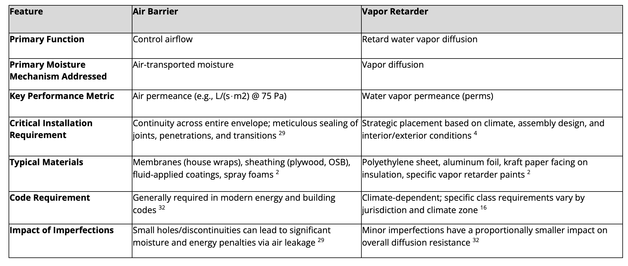
Table 1: Air Barrier vs. Vapor Retarder – A Functional Comparison
A critical source of ongoing confusion is the terminology itself. The term "vapor barrier," with its definitive "barrier" connotation, implies a more absolute and critical role in stopping all vapor movement than the more accurate term "vapor retarder," which reflects the function of managing diffusion rates.[13] This linguistic legacy subtly reinforces the notion that achieving a near-zero perm rating is a primary goal, overshadowing the more pressing need to stop air movement, which carries far more moisture.
The fact that some materials can function as both an air barrier and a vapor retarder (e.g., a meticulously sealed polyethylene sheet or continuous closed-cell spray foam) further blurs the functional distinctions in practice.[11] This can lead to the erroneous assumption that specifying a material for its vapor retarding properties automatically ensures adequate air barrier performance, or vice versa. However, the level of detailing and continuity required for an effective air barrier system is far more rigorous and unforgiving than what might be considered adequate for a vapor retarder whose primary role is to manage diffusion across its surface area.[29] A 10% discontinuity in a vapor retarder might mean it's 90% effective at retarding diffusion, but a 10% discontinuity in an air barrier system can lead to catastrophic failures in moisture and energy control.[32]
It is imperative for the design and construction industry to clearly separate the specification and performance targets for air control from those for vapor control. While integrated products and materials exist, the distinct functional requirements and, most importantly, the detailing for continuity of the air control layer, must be independently understood, specified, and meticulously executed to achieve desired building performance. Simply calling for a "vapor barrier" and hoping it also serves as an adequate air barrier is an approach fraught with risk.
The Primacy of Air Tightness: A Holistic Approach to Building Performance
Given that air leakage is overwhelmingly the dominant mechanism for moisture transport into and through building assemblies [1], the establishment of a continuous and robust air barrier system emerges as the single most critical strategy for effective moisture control. As building scientist Joseph Lstiburek succinctly states, "air barriers are a good idea everywhere, vapor barriers are not".[4] An effective air barrier minimizes the potential for condensation within the building envelope by preventing warm, moist air from reaching cold condensing surfaces.[12]
However, the importance of air tightness extends far beyond just moisture management. Achieving a high level of air tightness offers a multitude of interconnected benefits that contribute to overall building performance, occupant well-being, and long-term durability:
Energy Efficiency: This is perhaps the most widely recognized benefit. By minimizing uncontrolled air exchange (infiltration of outside air and exfiltration of conditioned inside air), air barriers significantly reduce heating and cooling loads. This translates directly to lower energy consumption, with potential reductions ranging from 10% to 40% in general buildings [29] and around 15% in homes designed to Zero Net Energy (ZNE) standards.31 Consequently, operational costs are lowered as HVAC systems do not have to work as hard to maintain desired indoor temperatures.[28]
Improved Comfort: Airtight buildings provide a more comfortable indoor environment by eliminating drafts and cold spots often associated with leaky envelopes.[31] This leads to more consistent and stable indoor temperatures throughout the conditioned space.
Enhanced Indoor Air Quality (IAQ): A continuous air barrier plays a crucial role in protecting IAQ by controlling the entry of outdoor pollutants such as dust, pollen, smoke, and soil gases like radon (which is primarily transported by air, not diffusion[7]).[29] Research indicates that airtight homes can reduce indoor concentrations of harmful PM2.5 particles by approximately 70% compared to conventional, leakier homes.[31] Furthermore, air tightness enables mechanical ventilation systems to operate much more effectively and predictably. Instead of relying on uncontrolled and often polluted air leakage paths, ventilation systems in tight buildings can provide the correct amount of fresh, filtered air from a known source, precisely managing indoor humidity and diluting internally generated pollutants.[31]
Building Durability: By significantly reducing the amount of moisture entering and moving through building assemblies via air leakage, air barriers mitigate the risk of moisture-related damage to building components. This includes preventing rot in wood framing, corrosion of metal components, and degradation of insulation materials, thereby extending the structure's lifespan and preventing premature failure of components.[28]
Acoustic Control: Well-sealed building envelopes can also contribute to improved sound isolation, reducing the transmission of exterior noise.[29]
The realization of these benefits hinges on one critical factor: the continuity and quality of workmanship of the air barrier system. Unlike vapor retarders, where minor imperfections might lead to a proportional decrease in diffusion resistance, the performance of an air barrier is fundamentally compromised by discontinuities.[32] As stated in one industry report, "The success of an air barrier system is highly dependent on skilled installation and adherence to detailed specifications. Because it is a barrier, any failure point can compromise the entire performance".[29] Many of you likely recognize the common failure points for air barriers, such as joints between materials, transitions between different assemblies (e.g., wall-to-roof, wall-to-foundation), and penetrations for windows, doors, pipes, and wiring.[29] Meticulous sealing of these areas using appropriate tapes, sealants, and gaskets is paramount, as is testing your results.[13] Achieving this level of continuity requires careful planning, coordination among trades, and a commitment to quality construction practices.[30]
The multiple, significant co-benefits derived from achieving superior air tightness—spanning energy savings, enhanced IAQ, improved durability, and greater occupant comfort—make it a far more impactful and cost-effective strategy to prioritize in building design and construction than a narrow focus on controlling vapor diffusion. Investing in a high-quality, continuous air barrier system yields substantial returns across a wide spectrum of building performance metrics. In contrast, an overemphasis on a specific class of vapor retarder primarily targets vapor diffusion, which is often a secondary moisture transport mechanism. When viewed through the broader lens of holistic building performance and lifecycle costs, the return on investment for achieving superior air tightness is demonstrably higher, making the historical "obsession" with vapor barriers appear even more disproportionate.
Interestingly, the very act of meticulously creating a continuous air barrier can often incidentally improve control over vapor diffusion, even if the primary air barrier material itself is vapor permeable (like many house wraps). Many pathways for air leakage, such as gaps at joints or around penetrations, also represent potential pathways for vapor diffusion if a vapor pressure differential exists across them. By diligently sealing these openings to achieve air control [29], one inherently reduces the surface area available for diffusion at these critical junctures. While the primary air barrier material might be designed to allow vapor to pass through it, the act of sealing its edges and integrating it continuously into the building envelope makes the overall assembly more resistant to all forms of gaseous transport through those specific, sealed leakage points. This implies that a dedicated focus on achieving comprehensive air tightness can indirectly bolster vapor control, whereas focusing solely on the perm rating of a vapor retarder does little to address the far more significant issue of air leakage.
This underscores the need for a shift in industry quality control and verification processes. While whole-building air leakage testing (e.g., blower door tests) is becoming more common and is mandated by some codes 28, the broader mindset shift towards viewing and executing "airtightness as a system" rather than merely installing an "air barrier product" is still developing. The emphasis on "construction quality and workmanship" 29 is far more critical for the successful performance of an air barrier system than it is for a vapor retarder.
The Importance of Dedicated Dehumidification
A core principle of durable building design is maintaining a moisture balance where the rate of moisture removal from an assembly consistently exceeds the rate of moisture entry. If wetting outpaces drying, moisture accumulation occurs, leading to degradation of materials, structural damage, and potential health issues from mold growth. While the strategies discussed previously—prioritizing air tightness and strategically using vapor retarders—are crucial for minimizing wetting, actively promoting drying is equally important, particularly in challenging conditions like a hot/humid climate.
In many modern, airtight homes, and especially in humid climates or buildings with high internal moisture loads (e.g., from occupants, cooking, construction moisture, etc.), relying solely on passive drying mechanisms (like vapor diffusion through permeable materials) or the incidental dehumidification provided by standard air conditioning systems may not be sufficient to ensure net drying. Air conditioning systems are primarily designed for sensible cooling (temperature control) and may not operate long enough or at optimal conditions to adequately remove latent moisture (humidity), especially during shoulder seasons or under partial load conditions.
This is where dedicated dehumidification systems play a critical role. These systems are designed specifically to remove excess moisture from the indoor air, thereby lowering the indoor relative humidity (RH). By maintaining a lower indoor RH (ideally between 30-60%, or even below 50%), a greater vapor pressure differential is established between the moist building materials and the drier indoor air. This enhanced differential significantly increases the drying potential of the assemblies towards the interior.
Benefits of Dedicated Dehumidification:
Enhanced Drying Capacity: Actively reduces indoor humidity, creating a more favorable gradient for moisture to move out of damp materials. This is crucial for drying incidental wetting from leaks, construction moisture, or even inward vapor drives that might bypass other defenses.
Improved Indoor Air Quality (IAQ) and Health: By maintaining lower RH, dedicated dehumidifiers help prevent conditions conducive to mold growth, dust mites, and other biological contaminants, which thrive in damp environments.
Occupant Comfort: Lower humidity levels are generally perceived as more comfortable, especially in warm weather.
Protection of Building Materials and Furnishings: Prevents moisture damage to structural components, insulation, finishes, and contents.
Complements Airtight Construction and Mechanical Ventilation: In highly airtight homes, where natural air exchange is minimal, mechanical ventilation (often with Energy Recovery Ventilators - ERVs) is essential for fresh air. While ERVs can help manage some moisture from incoming ventilation air, they do not actively dehumidify the interior space. Supplemental dehumidification works in tandem with these systems to ensure comprehensive moisture control.
Dedicated dehumidification systems can be whole-house units integrated with the HVAC system or standalone units. Their importance has become increasingly recognized, especially in high-performance building standards. Ensuring that the building can reliably dry out any moisture it encounters is a cornerstone of long-term durability (not to mention ensuring indoor air quality), and dedicated dehumidification provides a powerful tool to achieve this goal.
Strategic Use of Vapor Retarders: Necessary Caveats and Considerations
While air tightness is paramount, vapor retarders remain a necessary component of moisture control strategies in specific situations. Their use, however, must be guided by building science principles, particularly the critical need to facilitate drying. A fundamental principle of durable building envelope design is that assemblies should be designed to dry if they become wet, whether from incidental moisture intrusion or construction moisture.9 This necessitates the avoidance of "double vapor barriers"—impermeable layers on both the interior and exterior sides of an assembly—which can trap moisture and prevent drying in either direction.9 The building science consensus encourages "drying mechanisms over wetting prevention mechanisms" wherever feasible.[9]
The appropriate strategy for vapor control is highly dependent on climate and the type of cladding used.
Climate-Specific Needs for Vapor Control:
Extreme Cold Climates (e.g., ASHRAE/IECC Climate Zones 6, 7, 8, and Marine 4 in some instances):
Concern: Significant outward vapor drive from the warm, humidified interior to the cold exterior during winter, risking condensation on or within the cold exterior sheathing or other components of the wall assembly.[20]
Strategy: Typically, building codes mandate a Class I (e.g., polyethylene sheet, ≤0.1 perm) or Class II (e.g., kraft-faced insulation, > 0.1 to ≤1.0 perm) vapor retarder on the interior (warm-in-winter) side of framed walls.[10]
Nuances: Building scientist Joseph Lstiburek suggests that polyethylene (Class I) should generally be reserved for very cold hygro-thermal regions.[40] The addition of sufficient continuous exterior insulation can keep the wall cavity's condensing surfaces (like sheathing) warm enough to prevent condensation, potentially reducing or eliminating the need for a highly impermeable interior vapor retarder.[39] The IRC, for example, allows the use of Class III vapor retarders (e.g., latex paint, > 1.0 to ≤10 perms) in these cold zones if specific R-values of continuous exterior insulation are installed, or in some cases, with vented claddings.[17]
Hot-Humid Climates (e.g., ASHRAE/IECC Climate Zones 1A, 2A, parts of 3A):
Concern: Predominant vapor drive is from the hot, humid exterior to the cooler, air-conditioned interior during much of the year.[20]
Strategy: Interior vapor barriers (Class I or II) should generally be avoided to allow the wall assembly to dry towards the interior.[20] Some even emphatically claim that an interior polyethylene vapor barrier should "NEVER be installed" in these conditions if an exterior air/vapor barrier is present.[41] If an air/vapor barrier is used on the exterior (which can be beneficial for controlling bulk water and the strong inward vapor drive from outside), the wall assembly must be able to dry inwards. Lstiburek advocates for vapor-open assemblies in these climates, potentially with a vapor-permeable air control layer on the interior if masonry is part of the assembly.[44]
Mixed-Humid Climates (e.g., ASHRAE/IECC Climate Zones 3A, 4A, 4C):
Concern: Significant bi-directional vapor drive—outward in winter, inward in summer—makes the placement of a fixed, impermeable vapor barrier problematic.[4] A vapor barrier on the "wrong" side for part of the year can trap moisture.
Strategies:
"Smart" Vapor Retarders: These materials, such as CertainTeed MemBrain or ProClima Intello, have variable vapor permeance. They become more resistant to vapor diffusion (low perm) in dry conditions (typically winter interior) and more permeable (high perm) in humid conditions (typically summer, or if the cavity becomes wet).[45] For example, MemBrain is rated at ≤1 perm (dry cup) and > 10 perms (wet cup) [46], while Intello can range from < 0.13-0.23 perms to > 13 perms.[47] This adaptability allows drying in whichever direction is favored by the prevailing conditions.
Vapor-Open Assemblies: Designing walls to be generally vapor permeable on both sides of the insulation, often incorporating exterior continuous insulation. The primary moisture defense relies on the air barrier and bulk water management (flashing, drainage plane).[34]
Class II or Class III vapor retarders may be appropriate, as they allow a greater degree of drying than Class I materials.
Reservoir Claddings (e.g., Stucco, Brick, Stone, some Fiber Cement):
These claddings present a unique and critical challenge that demands specific attention beyond general climate-based rules.
The Challenge: Reservoir claddings absorb and store significant amounts of rainwater.24 When solar radiation subsequently warms the wet cladding, this stored moisture can be driven inward as a powerful vapor drive ("solar-driven inward vapor drive").[4] This inward pressure can overwhelm wall cavities, leading to condensation on interior layers, particularly if an impermeable interior vapor barrier like polyethylene is present and the building is air-conditioned.[55] This is a major caveat where focusing solely on controlling wintertime outward vapor drive from occupants is insufficient and potentially harmful.
Control Strategies for Inward Drive with Reservoir Claddings:
Ventilated Rainscreen/Cavity: A well-ventilated air space behind the cladding is a critical defense.[56] This gap (e.g., minimum 3/8 inch for many claddings, up to 1 inch or more for brick [56]) decouples the wet cladding from the rest of the wall assembly. It allows the inwardly driven moisture vapor to be carried away by airflow before it can penetrate the wall's weather-resistive barrier (WRB) and sheathing. Effective ventilation requires clear openings (vents) at both the top and bottom of the wall section.[56]
Appropriate WRB/Sheathing Permeance: The selection of the WRB and sheathing behind the ventilated cavity is crucial. In some designs, a WRB or sheathing with lower vapor permeance (acting as an exterior vapor control layer) might be used to "throttle" or resist the inward vapor drive.[56] However, this must be carefully balanced with the need for outward drying capability, especially in colder climates, to avoid creating a double vapor barrier situation.
Avoid Interior Impermeable Layers: In climates with significant air conditioning use, a Class I interior vapor retarder (like polyethylene) is generally contraindicated when reservoir claddings are present.[9] Such an interior barrier traps the solar-driven inward moisture, leading to condensation and potential damage. Lstiburek pointedly noted that the interior polyethylene sheets in many Vancouver condos in the 1980s and 1990s prevented the inward drying of rain-wetted stucco during the summer, contributing to widespread moisture problems.[40]
Additional Strategies: Reducing the reservoir capacity of the cladding itself by using paints or additives can lessen the inward drive potential.[58] Lstiburek advises that for reservoir claddings, one must either ventilate the airspace very effectively or use an exterior vapor throttle (like a dimple sheet behind the cladding) to intercept the inward drive; the key is that the air gap effectively uncouples the cladding from the wall assembly.[59]

Table 2: Vapor Retarder Strategies – Key Caveats and Considerations
The caveats for vapor retarder use are not minor exceptions. They represent common and critical construction scenarios, such as buildings with brick or stucco exteriors, or those located in the diverse climates across North America. In these situations, a simplistic "vapor barrier on the warm side" rule, often learned as a fundamental, can fail dramatically and cause significant harm if not critically assessed against the actual moisture physics at play.[14] The historical borderline obsession with vapor barriers may, in part, stem from an oversimplification of these complex interactions. When reservoir claddings are introduced, for example, solar-driven inward vapor drive becomes a powerful force that can overwhelm an assembly designed only to resist wintertime outward diffusion from occupant activities.[55] If the "warm side" rule is still rigidly applied with an interior polyethylene sheet in an air-conditioned building with a brick exterior, it inadvertently creates a moisture trap.[55] This demonstrates that the simple rule is insufficient for many common building types and that the borderline obsession might be with an incomplete rule itself, rather than a deep understanding of the building science that sometimes invalidates or modifies it.
The development and market presence of "smart" vapor retarders are a direct technological response to the documented failures of fixed-permeance vapor barriers in mixed climates or complex assemblies involving bi-directional vapor flow.[45] Their existence and promotion for challenging situations like mixed climates or unvented roof assemblies underscore that the "settled science" of moisture control includes acknowledging these complexities and providing advanced tools to address them. If traditional polyethylene (Class I) or kraft-facing (Class II) worked perfectly in all situations, there would be little impetus for materials that actively change their permeance in response to ambient humidity.[46] This reinforces that "settled science" does not equate to "simple science" in all applications of vapor control.
Ultimately, effective vapor control is less about finding a single perfect barrier material and more about understanding and managing vapor flow dynamics and drying potential within the entire building assembly, specific to its climate, materials, and operational conditions. This requires a significant shift from a product-centric thinking (i.e., "which vapor barrier product should I use?") to a system-centric, performance-based thinking (i.e., "how will this entire assembly manage all forms of moisture, including vapor, and ensure it can dry if it gets wet?").
Moving Forward: Prioritizing Air Tightness in Design and Construction
To align construction practices with established building science, the architecture and construction community must consciously shift its focus towards prioritizing air tightness. This requires changes in design philosophy, specification practices, on-site execution, and industry education.
Recommendations for the Architecture and Construction Community:
Prioritize Air Barrier System Design from Concept: The air barrier system should not be an afterthought or a layer simply added to the drawings. It must be a primary design consideration from the earliest conceptual stages. Designers need to clearly define the location of the continuous air control layer(s) and ensure this continuity is meticulously planned across all building assemblies and critical interfaces (e.g., wall-to-roof, wall-to-foundation, around penetrations).[29]
Specify for Air Tightness Performance, Not Just Products: Specifications should move beyond merely naming an air barrier material. They should include measurable air tightness targets for the whole building (e.g., a specific ACH50 value) and potentially for assemblies or components. Crucially, specifications must mandate verification through quantitative testing, such as whole-building blower door tests.[28] This shifts the focus from simply installing a product to achieving a verifiable performance outcome. Consider using the Phius performance standard for high levels of quality assurance and quality control.
Invest in Education and Training: Continuous education for design professionals, project managers, and construction crews is essential. This training should cover current building science principles related to air leakage, moisture transport mechanisms, the appropriate and strategic use of vapor retarders, and importantly, how to correctly detail and install air barrier systems.[30] Efforts should be made to actively address and debunk persistent misconceptions surrounding vapor barriers and air barriers.[40]
Develop and Implement Robust Detailing for Continuity: The success of an air barrier system lies in its continuity. Architects and designers must develop robust, practical, and buildable details for all penetrations, joints, and transitions between different air barrier materials or building assemblies. These details are where systems most commonly fail.[29]
Shift Mindset from "Vapor Barrier" to "Vapor Management": The industry needs to internalize that vapor control is about managing diffusion rates appropriate to the specific climate and assembly, not just about stopping all vapor movement with an impermeable layer. This involves embracing strategies like vapor-open assemblies or the use of smart vapor retarders where these approaches enhance the overall drying potential and resilience of the building envelope.[9]
Critically Evaluate "Rules of Thumb" and Historical Practices: Long-standing practices and simplified rules regarding vapor barrier placement should be critically examined against current building science. Decisions must be based on climate-specific, assembly-specific hygrothermal analysis rather than outdated or overly generalized guidelines.
The Role of Building Codes and Standards:
Building codes and industry standards play a vital role in driving practice. Continued advocacy for and support of code advancements that emphasize verifiable air tightness performance are necessary. Codes should also provide clear, science-based, and nuanced guidance on vapor retarder selection and placement, moving away from potentially problematic or overly simplistic blanket requirements. The evolution of codes to include mandatory air barrier requirements and air leakage testing is a positive development.[32] Standards like ASHRAE 90.1, which already mandate continuous air barriers with specific maximum air leakage rates for materials, assemblies, and whole buildings, provide a robust framework that can be more broadly adopted and rigorously enforced.[35]
Achieving a genuine shift in industry focus towards air tightness requires more than just better products; it demands better processes. From the initial design integration and clarity of specifications to the crucial inter-trade coordination and robust quality assurance/quality control (QA/QC) measures on the construction site, air tightness is a systems challenge.[29] It is not about a single product's performance in isolation but about how multiple components and materials are meticulously assembled by various trades to form a continuous, unbroken plane of air control. Therefore, simply specifying an "air barrier material" is insufficient. The design must explicitly show how this material connects and remains continuous across the entire envelope; trades must be trained in the specific techniques required for its correct installation; and site inspections, coupled with diagnostic testing, must verify that the intended performance is achieved.
This process-oriented approach is inherently more demanding than the simpler, often less critical, task of specifying and installing a sheet of polyethylene as a "vapor barrier."
The historical lack of widespread, rigorous air barrier verification (though this is improving with more stringent code requirements for testing [32]) has arguably allowed suboptimal air sealing practices to persist. Without consistent measurement and accountability for air tightness performance, the perceived urgency to perfect it may remain lower than its actual importance warrants. If air tightness is not consistently tested and failures are not identified and rectified [28], then the often severe consequences of poor air barrier detailing (e.g., hidden moisture damage, high energy bills, poor IAQ) are less immediately visible than, for instance, a bulk water leak from a poorly flashed window. This lack of immediate, obvious feedback can foster complacency or lead to a continued underestimation of air leakage's multifaceted impact, thereby allowing the "vapor barrier obsession" to continue as a more visible, albeit often less critical, focal point of moisture control discussions.
Ultimately, shifting the industry's predominant focus from vapor barriers to air tightness is a cultural transformation as much as a technical one. It will require a concerted and sustained effort involving designers (who must prioritize and detail for air continuity), builders and contractors (who must ensure meticulous execution and implement effective QA/QC), code officials (who must understand and enforce air tightness standards more rigorously), and even manufacturers (who should provide clearer guidance on system integration rather than focusing solely on individual product features).
A Call for a Science-Based Shift in Focus
The evidence from decades of building science research and field experience is unequivocal: air tightness is the most critical factor in controlling moisture transport through building assemblies in the majority of construction scenarios. The quantity of moisture carried by air leakage far surpasses that transported by vapor diffusion.[1] This fundamental understanding necessitates a paradigm shift in the architecture and construction community—a move away from an often disproportionate and historically rooted fixation on vapor barriers towards the primacy of designing and constructing robust, continuous air barrier systems.
This is not to say that vapor retarders have no role. They are indeed necessary tools, but their application must be strategic, nuanced, and firmly grounded in current building science. The "settled science" provides clear, climate-specific and assembly-specific guidance for their appropriate use, particularly in extreme cold climates and when dealing with the complexities of reservoir claddings and solar-driven inward vapor drive.[14] This modern understanding moves far beyond outdated, overly simplistic blanket rules that can, in many common situations, lead to moisture-related building failures by trapping moisture or impeding necessary drying.
Adopting a holistic, science-informed approach that prioritizes a continuous air barrier system, coupled with intelligent and context-appropriate vapor management strategies, offers profound benefits. Such an approach leads to buildings that are significantly more durable, energy-efficient, and provide healthier indoor environments for their occupants.[28] This shift not only reduces the risk of costly moisture-related failures and repairs but also improves occupant comfort and optimizes the allocation of resources in both design and construction phases.
The near obsession with vapor barriers is not merely an academic debate; it has tangible real-world consequences, contributing to building failures, energy waste, and compromised occupant health when it distracts from the more pressing need for air tightness.[28] Therefore, the advocated shift in focus is not just a technical correction but a matter of professional responsibility for those involved in creating the built environment.
It is time for the architecture and construction community to collectively move beyond the prolonged and often misdirected preoccupation with vapor barriers. Instead, the industry must embrace the well-established primacy of air tightness as the cornerstone of effective moisture control and overall building performance. Successfully making this transition will not only prevent common building problems but will also enhance the reputation and value proposition of the AEC industry by consistently delivering buildings that perform better, last longer, and truly align with the robust body of knowledge developed by the building science community. This alignment is crucial for creating a more sustainable, resilient, and healthy built future.
Works cited
Air Barrier vs Vapor Barrier: What are The Differences, accessed May 12, 2025, https://barricadebp.com/news/air-barriers-vs-vapor-barriers
Air Barrier vs Vapor Barrier- What You NEED to Know - Healthy Building Science, accessed May 12, 2025, https://healthybuildingscience.com/2024/02/01/air-barrier-vs-vapor-barrier-what-you-need-to-know/
Vapor barrier - Wikipedia, accessed May 12, 2025, https://en.wikipedia.org/wiki/Vapor_barrier
buildingscience.com, accessed May 12, 2025, https://buildingscience.com/sites/default/files/migrate/pdf/RR-0004_Air_Barrier_Vapor_Barrier.pdf
ENERGY SERIES: What about Moisture? | VCE Publications ..., accessed May 12, 2025, https://www.pubs.ext.vt.edu/2908/2908-9020/2908-9020.html
Understanding Moisture Flow | CertainTeed, accessed May 12, 2025, https://www.certainteed.com/inspiration/case-studies/understanding-moisture-flow
Air Barrier or Vapor Barrier? - Building Science Podcast ..., accessed May 12, 2025, https://www.greenbuildingadvisor.com/article/air-barrier-or-vapor-barrier-building-science-podcast
Controlling condensation from air leakage and vapour diffusion ..., accessed May 12, 2025, https://www.constructioncanada.net/controlling-condensation-from-air-leakage-and-vapour-diffusion/
BSD-106: Understanding Vapor Barriers | buildingscience.com, accessed May 12, 2025, https://buildingscience.com/documents/digests/bsd-106-understanding-vapor-barriers
Understanding Vapor Barriers - VaproShield, accessed May 12, 2025, https://vaproshield.com/images/stories/pdf/joe%20lstiburek%20understanding%20vapor%20barriers%20ashrae%202004%2008.pdf
BSI-084: Forty Years of Air Barriers\*—The Evolution of the ..., accessed May 12, 2025, https://buildingscience.com/documents/insights/bsi-084-forty-years-of-air-barriers
Moisture Transfer through Walls, accessed May 12, 2025, https://web.ornl.gov/sci/buildings/conf-archive/1989%20B4%20papers/044.pdf
www.southface.org, accessed May 12, 2025, https://www.southface.org/wp-content/uploads/2019/08/N082-Building-Science-101.pdf
Vapor Barriers or Vapor Retarders - Department of Energy, accessed May 12, 2025, https://www.energy.gov/energysaver/vapor-barriers-or-vapor-retarders
Building Science Digest 106 Understanding Vapor Barriers - andrew.cmu.ed, accessed May 12, 2025, https://www.andrew.cmu.edu/course/48-400/pdfs/Understanding%20Vapor%20Barriers.pdf
Vapor Barrier Code Requirements: Crawl Space & Building… | Polyguard, accessed May 12, 2025, https://polyguard.com/blog/vapor-barrier-code-requirements
2021 International Building Code (IBC) - CHAPTER 14 EXTERIOR WALLS - 1404.3 Vapor retarders., accessed May 12, 2025, https://codes.iccsafe.org/s/IBC2021P1/chapter-14-exterior-walls/IBC2021P1-Ch14-Sec1404.3
2021 International Residential Code (IRC) - CHAPTER 7 WALL ..., accessed May 12, 2025, https://codes.iccsafe.org/s/IRC2021P3/chapter-7-wall-covering/IRC2021P3-Pt03-Ch07-SecR702.7
Moisture Control | Vapor Retarders, Residential, Installing - Insulation Institute, accessed May 12, 2025, https://insulationinstitute.org/im-a-building-or-facility-professional/residential/installation-guidance-2/moisture-management/vapor-retarders/
www.iccsafe.org, accessed May 12, 2025, https://www.iccsafe.org/wp-content/uploads/proclamations/TN06-Vapor-Retarders_pdf.pdf
i LABORATORY Moisture Control Handbook - UNT Digital Library, accessed May 12, 2025, https://digital.library.unt.edu/ark:/67531/metadc696747/m2/1/high_res_d/586594.pdf
Moisture Ingress in Building Envelope Materials: (II) Transport Mechanisms and Practical Mitigation Approaches - MDPI, accessed May 12, 2025, https://www.mdpi.com/2075-5309/15/5/762
buildingscience.com, accessed May 12, 2025, https://buildingscience.com/sites/default/files/migrate/pdf/BSD-106_Understanding%20Vapor%20Barriers_2013.pdf
Vapor Barriers and Wall Design - Building Science, accessed May 12, 2025, https://buildingscience.com/sites/default/files/migrate/pdf/RR-0410_Vapor_Barriers_Wall_Design.pdf
Building Science Digest 106 Understanding Vapor Barriers - revfoam insulation, accessed May 12, 2025, https://revfoam.com/wp-content/uploads/2015/01/BSD-106_Understanding-Vapor-Barriers_2013.pdf
Controlling Moisture Movement in Buildings - W. R. Meadows, accessed May 12, 2025, https://www.wrmeadows.com/data/cat-mm03.pdf
Moisture accumulation in walls due to air leakage, accessed May 12, 2025, https://publications-cnrc.canada.ca/eng/view/ft/?id=aebbca87-8deb-4f03-9ca9-ba27712f9297
The Role of Air Barriers in Modern Construction - Intertek, accessed May 12, 2025, https://www.intertek.com/blog/2025/02-25-air-barriers-in-modern-construction/
The impact of air barriers in meeting new energy codes - Salas O'Brien, accessed May 12, 2025, https://salasobrien.com/news/energy-code-air-barrier/
Common Air Barrier Failures and How to Avoid Them, accessed May 12, 2025, https://475.supply/blogs/design-construction-resources/common-air-barrier-failures-and-how-to-avoid-them
Benefits of Superior Airtightness - SVACH, accessed May 12, 2025, https://svach.lbl.gov/benefits-superior-airtightness/
The Last Word (We Hope) on Vapor Barriers | JLC Online, accessed May 12, 2025, https://www.jlconline.com/how-to/insulation/the-last-word-we-hope-on-vapor-barriers_o
Air Barrier vs Vapor Barrier: Key Differences, Benefits - METALCON 2025, accessed May 12, 2025, https://metalcon.com/blog/air-barrier-vs-vapor-barrier-how-do-they-differ/
BSC Information Sheet 311 Vapor Open Assemblies - Building Science, accessed May 12, 2025, https://buildingscience.com/sites/default/files/migrate/pdf/BSCInfo_311_Vapor_Open_Assemblies.pdf
ANSI/ASHRAE/IES Standard 90.1-2019: Envelope - Oregon.gov, accessed May 12, 2025, https://www.oregon.gov/bcd/codes-stand/Documents/90.1-2019-Envelope-training.pdf
Tight Air-Sealed Homes | Building Science Education, accessed May 12, 2025, https://bsesc.energy.gov/energy-basics/tight-air-sealed-homes
BSC Information Sheet 311 - Vapor Open Assemblies, accessed May 12, 2025, https://www1.eere.energy.gov/buildings/publications/pdfs/building_america/vapor_open_assemblies.pdf
PA-0401: Built Wrong from the Start | buildingscience.com, accessed May 12, 2025, https://buildingscience.com/documents/published-articles/pa-built-wrong-from-start/view
Is vapour barrier a bad idea for a house that has cold winters and hot humid summers?, accessed May 12, 2025, https://www.reddit.com/r/Homebuilding/comments/1gr4l4a/is_vapour_barrier_a_bad_idea_for_a_house_that_has/
Vapor Barrier Confusion : r/buildingscience - Reddit, accessed May 12, 2025, https://www.reddit.com/r/buildingscience/comments/1jhgu31/vapor_barrier_confusion/
www.carlisleccw.com, accessed May 12, 2025, https://www.carlisleccw.com/download.aspx?id=797&fileID=37
Vapor Barrier and humidity : r/buildingscience - Reddit, accessed May 12, 2025, https://www.reddit.com/r/buildingscience/comments/1784d5b/vapor_barrier_and_humidity/
The Truth About Vapor Permeability in High Humidity Environments - DuPont, accessed May 12, 2025, https://www.dupont.com/content/dam/dupont/amer/us/en/performance-building-solutions/public/documents/en/bsb-the-truth-about-vapor-permeability-43-d100849-enna.pdf
Building America Webinar: Stump the Building Science Chump — Joe Lstiburek (Text Version) | Department of Energy, accessed May 12, 2025, https://www.energy.gov/eere/buildings/building-america-webinar-stump-building-science-chump-joe-lstiburek-text-version
Vapour Barrier or Vapour Retarder? (Exposing important myths and ..., accessed May 12, 2025, https://litebox.ca/vapour-barrier-or-vapour-retarder-exposing-important-myths-and-misconceptions/
MemBrain™ | CertainTeed, accessed May 12, 2025, https://www.certainteed.com/products/building-insulation-products/membrain
Smart Vapor Retarders for Walls and Roofs - Fine Homebuilding, accessed May 12, 2025, https://www.finehomebuilding.com/project-guides/insulation/smart-vapor-retarders-for-walls-and-roofs
Understanding Air Barriers and Vapor Retarders: Why and Where to Place Them - Hypo Air, accessed May 12, 2025, https://hypoair.com/blogs/news/understanding-air-barriers-and-vapor-retarders-why-and-where-to-place-them
Reinforced all-round hydrosafe® high-performance vapour check - INTELLO X PLUS | pro clima international, accessed May 12, 2025, https://proclima.com/products/internal-sealing/intello-x-plus/technical-specs
Technical specs - INTELLO | pro clima international, accessed May 12, 2025, https://proclima.com/products/internal-sealing/intello/technical-specs
MemBrain™, The SMART Vapor Retarder - IDI: Insulation, accessed May 12, 2025, https://www.idi-insulation.com/wp-content/uploads/2020/06/MemBrain-SMART-Vapor-Retarder.pdf
Cetainteed MemBrain Vapor Retarder (All Sizes) - Shop Online - Insulation4US, accessed May 12, 2025, https://insulation4us.com/products/cetainteed-membrain-vapor-retarder-all-sizes
Pros and cons of a "vapor open" exterior wall assembly with/without rigid sheathing?, accessed May 12, 2025, https://www.greenbuildingadvisor.com/question/pros-cons-of-a-vapor-open-exterior-wall-assembly-with-without-rigid-sheathing
Joe Lstiburek Discusses Basement Insulation and Vapor Retarders - GreenBuildingAdvisor, accessed May 12, 2025, https://www.greenbuildingadvisor.com/article/joe-lstiburek-discusses-basement-insulation-and-vapor-retarders
RR-0104: Solar Driven Moisture in Brick Veneer | buildingscience.com, accessed May 12, 2025, https://buildingscience.com/documents/reports/rr-0104-solar-driven-moisture-in-brick-veneer/view
www1.eere.energy.gov, accessed May 12, 2025, https://www1.eere.energy.gov/buildings/publications/pdfs/building_america/reservoir_cladding.pdf
Brick, Stucco, Housewrap and Building Paper, accessed May 12, 2025, https://buildingscience.com/sites/default/files/migrate/pdf/RR-0105_Brick_Stucco_Housewrap_Paper.pdf
BSI-091: Flow-Through Assemblies | buildingscience.com, accessed May 12, 2025, https://buildingscience.com/documents/building-science-insights-newsletters/bsi-091-flow-through-assemblies
How to Protect Stucco Buildings from Moisture | Dr. Joe Lstiburek - YouTube, accessed May 12, 2025, https://www.youtube.com/watch?v=fBj4l3pzmss
Vapor Barrier Myths and Facts - Basement Waterproofing by Al, accessed May 12, 2025, https://basementwaterproofingbyal.com/waterproofing/vapor-barrier-myths-facts/